How to Use a Multimeter Complete Beginner Guide 2026
June 11th , 2026 | AstroAI *
Beginner's Guide • Multimeters • Symbols & Dial Positions
How to Use a Multimeter: Symbols, Dial Positions, and Probe Jacks Explained
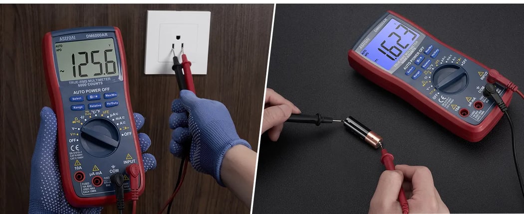
You opened the box, connected the probes, and now you are looking at a dial covered in abbreviations, symbols, and numbers that may not feel obvious yet. That is normal: a modern digital multimeter condenses many measurement functions onto one rotary knob. This guide explains the display, dial positions, probe jacks, and buttons in plain language, using the AstroAI DM6000AR as the reference model.
Quick Reference — The Five Rules Every Beginner Must Know
- Black probe → COM for standard measurements. The black lead normally stays in the COM jack; the red lead changes based on the function.
- Red probe location changes by function. Voltage and resistance: INPUT (VΩ) jack. Current: use the μA/mA or 10A jack only within the printed meter rating and user manual limit.
- V⁻⁻ = DC voltage, V~ = AC voltage. Batteries, car, USB = DC. Wall outlets and appliance supply lines are AC, but mains testing should only be done by trained users using properly rated equipment.
- Never measure current in parallel across a power source. Current must be measured in series with the circuit; putting the meter across a battery, outlet, or power supply while set for current can blow a fuse or damage the meter.
- De-energize before resistance, continuity, diode, or capacitance tests. Live voltage in these modes can give incorrect readings and may damage the meter.
Safety Notice
This guide is intended for basic low-voltage and beginner-level multimeter use. Do not test wall outlets, electrical panels, or high-voltage circuits unless you are trained, understand the meter and probe ratings, and follow applicable electrical safety requirements. When in doubt, contact a qualified electrician. Current measurement must be done in series, never in parallel across a power source. Always de-energize circuits before measuring resistance, continuity, diodes, or capacitance, and discharge capacitors before testing.
1. Anatomy of the AstroAI DM6000AR — What Is What
Before reading individual symbols, it helps to understand the three main zones of a digital multimeter: the display, the rotary dial, and the input jacks. Between them, they control everything the meter does.
AstroAI DM6000AR — 6000-count True-RMS
Zone 1 — The LCD Display
The large backlit display shows the main numeric reading plus a row of small indicator icons along the top and left edges. These icons tell you which mode is active, whether auto-ranging is on, whether Hold is active, and what unit the reading is in. A full breakdown appears in Section 2.
Zone 2 — The Rotary Dial
The central dial selects the measurement function. Turn it to any labeled position to activate that mode. The DM6000AR also has six push buttons above and below the display that modify behavior within each mode — they do not change the basic function, but adjust how it works. Full dial map in Section 3.
Zone 3 — The Input Jacks
The bottom of the meter has four labeled holes where the test leads plug in. Each jack has specific functions and maximum input ratings printed next to it. Using the wrong jack for current measurement is one of the most common beginner mistakes and can blow a fuse or damage the meter. Full jack guide in Section 4.
2. Every Symbol on the LCD Display — Explained
The display tells you more than the main number. Before trusting a reading, check the small icons around it; they show the active mode, unit, range behavior, and warning states.
2.1 Top Row — Mode and Status Indicators
| Symbol on Display | Full Name | What It Means | When You See It |
|---|---|---|---|
| AUTO | Auto-Ranging | The meter is automatically selecting the best measurement range. You do not need to set a range manually. | When auto-ranging is enabled (default on most modes) |
| APO | Auto Power-Off | The meter can automatically shut off after a period of inactivity to preserve battery life. | Always on by default; can be disabled on some models |
| H (or HOLD) | Data Hold | The current reading is frozen on the display. The meter stops updating even if the measured value changes. | After pressing the H/☀ button; useful when probing in awkward spaces |
| △ (triangle) | Relative Mode (REL) | The display shows the difference between the current reading and a stored reference value. The reference is set when you press Relative. | After pressing the Relative button; useful for nulling out lead resistance |
| USB | Model-Specific USB Indicator | May indicate USB-related status on versions that support data connection. Check the user manual for your exact model. | When supported by the specific meter version |
| ⊃→ (bar + arrow) | Continuity Mode | The meter is in continuity test mode. A beep will sound if a complete electrical path is detected (resistance below the threshold). | When continuity function is selected via the dial or Select button |
| →| (arrow + bar) | Diode Test Mode | The meter applies a small voltage and measures forward voltage drop across a diode or LED. Many standard silicon diodes show a forward voltage reading around 0.4–0.7 V, but the expected value depends on the diode type and test conditions. | When diode function is selected; shares a dial position with continuity |
| ·))) (waves) | Audible Continuity Beeper Active | The buzzer is enabled. If continuity exists, the meter will beep in addition to showing the reading. | Alongside the continuity symbol when beeper is active |
| °C / °F | Temperature Unit | Shows whether the temperature reading is displayed in Celsius or Fahrenheit. Toggle with the Select or Hz/Duty button depending on the model. | When the dial is set to °C/°F and a thermocouple probe is connected |
| % | Duty Cycle | Displays the duty cycle of a PWM (pulse-width modulated) signal as a percentage. 50% = signal is high half the time. | After pressing Hz/Duty button when measuring frequency |
| MAX / MIN | Maximum / Minimum Hold | The meter is tracking and holding the highest (MAX) and lowest (MIN) readings since the function was activated. | After pressing the Max/Min button; cycle between MAX, MIN, and real-time by pressing again |
| 🔋 (battery icon) | Low Battery Warning | The internal battery is running low. Replace the 9V battery before making precision measurements — low battery can affect reading accuracy. | When battery voltage drops below the threshold (typically ~7.5 V for a 9V cell) |
2.2 Left-Side Display Symbols — Signal and Mode Type
| Symbol | Meaning | When You See It |
|---|---|---|
| ⁻⁻⁻ (solid line + dashes) | DC (Direct Current). The signal being measured is steady-polarity DC — batteries, car electrical, USB power, solar panels. | In voltage (V⁻⁻) or current (A, mA) DC modes |
| ~ (sine wave) | AC (Alternating Current). The signal alternates polarity — wall outlets, appliances, generators, transformer outputs. | In voltage (V~) or AC current modes |
| 🔋 (left edge) | Battery status / low battery indicator. Indicates battery condition or low-battery warning depending on the display state. Replace the battery when the low-battery symbol appears. | Always during normal operation; flashes or changes when battery is low |
2.3 Unit Suffixes — What MKΩHz mAVnF Mean
Unit suffixes explain the scale of the number on screen. The same digits can mean very different things depending on whether the display shows V, mV, Ω, kΩ, A, mA, nF, or μF.
| Displayed Unit | Meaning | Example Reading | Typical Context |
|---|---|---|---|
| V | Volts | 12.64 V | Car battery, wall outlet |
| mV | Millivolts (1/1000 V) | 450 mV | Small voltage drops, sensor signals, diode forward voltage |
| A | Amperes (Amps) | 3.2 A | Car fuse circuits, high-draw loads |
| mA | Milliamperes (1/1000 A) | 47.3 mA | LED current, small electronics |
| μA | Microamperes (1/1,000,000 A) | 220 μA | Sensor bias currents, leakage measurement |
| Ω | Ohms (resistance) | 330 Ω | Resistors, wire resistance, sensor resistance |
| kΩ | Kilohms (1,000 Ω) | 4.7 kΩ | Pull-up resistors, signal resistors |
| MΩ | Megohms (1,000,000 Ω) | 2.2 MΩ | Insulation resistance, high-value resistors |
| Hz | Hertz (frequency, cycles per second) | 60 Hz / 1.2 kHz | AC mains frequency, PWM signals, motor speed |
| kHz / MHz | Kilohertz / Megahertz (higher frequencies) | 38.4 kHz / 10 MHz | UART baud rates, RF signals, oscillator outputs |
| nF | Nanofarads (capacitance, 1/1,000,000,000 F) | 100 nF | Film and ceramic capacitors in electronics |
| μF | Microfarads (1/1,000,000 F) | 470 μF | Electrolytic capacitors in power supplies |
| mF | Millifarads (1/1,000 F) | 10 mF | Large motor run capacitors, supercapacitors |
3. Every Dial Position on the DM6000AR — Complete Function Map
Before taking a measurement, confirm two things: which dial position you need and where the red probe should be plugged in. The table below maps each DM6000AR dial position to its function, jack, rating, and common use case.
| Dial Label | Function | Red Probe Jack | Max Input | Typical Use Cases |
|---|---|---|---|---|
| OFF | Meter off | — | — | Always turn to OFF when not in use to preserve battery |
| V⁻⁻ | DC Voltage — measures steady-polarity voltage | INPUT (VΩ) | 1000 V DC | Car battery (12 V), AA/AAA/9V batteries, USB 5 V, solar panels, car fuse box voltage, ECU sensor voltage |
| V~ | AC Voltage — measures alternating voltage | INPUT (VΩ) | 750 V AC | Wall outlets (120/240 V), appliance supply lines, generator output, extension cord live-end check |
| Ω / →| / ·))) | Resistance / Diode / Continuity — three functions on one position; toggle with Select button | INPUT (VΩ) | Do not apply voltage | Ω: measuring resistors, wiring resistance, motor windings | →|: testing diodes and LEDs | ·))): fuse check, switch check, wire continuity |
| Hz / Duty | Frequency and Duty Cycle — measures signal frequency in Hz and duty cycle % of PWM signals | INPUT (VΩ) | 0–60 MHz | Verifying AC mains frequency (should be 60 Hz in USA), measuring PWM fan speed controllers, testing oscillators, checking motor drive frequency |
| °C / °F | Temperature — measures temperature via K-type thermocouple probe (not included, sold separately) | INPUT jack (thermocouple) | Supported; exact range depends on the thermocouple and user manual specifications | HVAC duct temperature, coolant temperature, soldering iron tip verification, engine bay thermal checks |
| μA≃ | Microamp AC/DC Current — measures very small currents in microampere range | μA mA jack | Use within the printed meter rating and user manual limit | Sensor bias current, leakage current, microcontroller sleep-mode current draw |
| mA≃ | Milliamp AC/DC Current — measures low current within the meter rating | μA mA jack | Use within the printed meter rating and user manual limit | LED current consumption, small motor current, USB device draw, parasitic drain search (initial check) |
| A≃ | High-Amp AC/DC Current — measures currents up to 10 A | 10A jack (left red jack) | Up to 10A; follow the time limit in the user manual | Low-voltage DC current checks up to 10 A, small accessory loads, solar charge current within the meter rating |
| ⊃| (capacitor symbol) | Capacitance — measures capacitor value in nF, μF, or mF | INPUT (VΩ) | 60 μF – 20 mF | Testing electrolytic capacitors for ESR/value degradation, verifying capacitor values in electronics repair, checking motor run capacitors |
Important: The ≃ symbol on current positions
On the DM6000AR, the ≃ symbol after μA, mA, and A indicates that both AC and DC current can be measured in that position. The display will show AC or DC depending on which sub-function is active. Press the Select button to toggle between AC and DC measurement in current modes.
4. The Four Input Jacks — Where to Plug Each Probe
The probe jacks decide how the meter is connected internally. For most beginner measurements the black lead stays in COM and the red lead goes to INPUT, but current measurements require moving the red lead and inserting the meter in series with the circuit.
| Jack Label | Probe Color | Used For | Maximum Rating | Warning |
|---|---|---|---|---|
| 10A | Red | High-current measurement only (A≃ dial position). Current up to 10 amps. | Up to 10A; follow the time limit in the user manual | Use the 10A jack only within the meter's printed rating and the time limit specified in the user manual. |
| μA mA | Red | Low-current measurement (μA≃ and mA≃ dial positions). | Use within the printed meter rating and user manual limit | Use the μA/mA jack only within the current rating printed on the meter and specified in the user manual. |
| COM | Black | Common reference point for standard measurements. The black lead normally goes here. | Check the rating printed on the meter and user manual | For standard measurements, keep the black lead in COM so the meter has a stable reference point. |
| INPUT (VΩ) | Red | Voltage (V~ and V⁻⁻), resistance (Ω), continuity, diode test, capacitance, frequency, temperature — everything except current. | Follow the rating printed on the meter and test leads | Do NOT use this jack for current measurements. Move the red lead to μA mA or 10A, then insert the meter in series with the circuit. |
The One-Sentence Probe Rule
For standard measurements, black goes to COM. Red goes to INPUT for voltage, resistance, continuity, diode, capacitance, frequency, and temperature, then moves to μA mA or 10A only for current measurements.
5. The Six Buttons — What Each One Does
The buttons refine what the selected dial mode does. Use them after the dial and probe jacks are correct; they help with range selection, held readings, min/max capture, relative measurements, and frequency or duty-cycle checks.
| Button Label | Primary Action | When to Use It | Practical Example |
|---|---|---|---|
| Select | Cycles through sub-functions within the current dial position. In the Ω position: toggles between Resistance → Diode → Continuity. In current modes: toggles AC/DC. | Whenever the dial has multiple functions on one position | You want to test continuity: turn dial to Ω, then press Select until ·))) appears on the display |
| H / ☀ (Hold / Backlight) | Short press: freezes the current reading on the display (Data Hold). Long press: toggles the backlight, depending on the meter settings. | Hold: when probing in an awkward position where you cannot watch the screen. Backlight: dark engine bays or electrical panels | Insert probe into a junction box, press H to freeze reading, withdraw probes, read the display safely |
| Max/Min | Activates maximum/minimum tracking. The meter continuously records the highest and lowest reading. Press again to cycle between showing MAX, MIN, and current live value. | When you need to capture a peak or lowest value over time | Battery cranking test: press Max/Min before cranking so the meter captures the lowest voltage dip during engine start without you having to watch the display |
| Range | In Auto mode: switches from auto-ranging to manual range selection, then cycles through available ranges. Useful when the auto-range is too slow for rapidly changing signals. | When measuring a known range and wanting faster response, or when testing on a specific range for fine resolution | Measuring a known low-voltage source: select an appropriate manual range if you want a steadier display or finer reading within the meter's rated range |
| Relative | Stores the current reading as a reference value. Subsequent readings display only the difference from that reference. Press again to clear. The △ symbol appears on the display when active. | When you want to measure change relative to a baseline, or to null out the test lead resistance in resistance measurements | Short the two probes together, press Relative to zero the lead resistance, then the resistance reading will be accurate to the component only |
| Hz/Duty | In voltage or current modes: activates frequency measurement overlay. Press again to toggle to duty cycle (%) display. | When measuring AC voltage and also wanting to see the signal frequency, or when checking PWM duty cycles | Set to V~ on a wall outlet, press Hz/Duty to confirm the AC frequency is 60 Hz (USA) or 50 Hz (Europe) |
6. Step-by-Step Instructions for Common Measurements
These walkthroughs cover beginner-friendly tasks such as batteries, low-voltage circuits, continuity, and components. For wall outlets, panels, or unknown circuits, confirm ratings first and use trained help when the risk is unclear.
6.1 Measuring DC Voltage (V⁻⁻) — Batteries and Car Circuits
DC voltage is the safest first measurement to learn because the meter is placed across the power source, not inside the circuit path. Use this mode for common battery and low-voltage checks within the meter's rating.
- Insert black lead into COM, red lead into INPUT.
- Turn dial to V⁻⁻ (DC Voltage).
- Confirm AUTO appears on the display (or manually select a range above the expected voltage).
- Touch red probe to the positive (+) terminal, black probe to the negative (−) terminal.
- Read the voltage. A positive reading confirms correct polarity. A negative reading means probes are reversed — the measurement is still correct in magnitude.
6.2 Measuring AC Voltage (V~) — Wall Outlets and Appliances
AC voltage checks can involve hazardous mains power. Beginners should practice on low-voltage sources first and should only test outlets or appliance supply lines when they understand the meter, probe, and category ratings.
- Insert black lead into COM, red lead into INPUT.
- Turn dial to V~ (AC Voltage).
- For trained outlet checks, keep fingers behind the probe guards and place the probes only on the intended test points. Polarity does not matter for a basic AC voltage reading.
- Read the voltage. USA standard outlet = 110–120 V AC. European outlets = 220–240 V AC.
6.3 Measuring Resistance (Ω)
Resistance mode sends a small test signal from the meter through the component. The circuit must be off and isolated enough for the reading to represent the part you are testing.
- Power off and, when practical, disconnect the component from the circuit. Live voltage gives unreliable readings and can damage the meter.
- Insert black into COM, red into INPUT.
- Turn dial to Ω position. Press Select if needed until the Ω symbol appears (not →| or ·))).
- For precision: short the probes and press Relative to zero out lead resistance, then measure the component.
- Touch probes to both leads of the component. "OL" or "1" means resistance is higher than the current range — press Range to go higher, or let auto-range step up.
6.4 Testing Continuity (·)))
Continuity mode is useful for checking whether a wire, fuse, switch, or trace has a complete path. It is a powered-off test, so confirm the circuit is de-energized before using it.
- De-energize the component completely.
- Insert black into COM, red into INPUT.
- Turn dial to Ω. Press Select until the ·))) symbol appears on the display.
- Touch the two probes together to self-test — you should hear a beep.
- Touch one probe to each end of the wire, fuse, or switch. Beep = complete circuit (good). Silence + OL = open circuit (blown or broken).
6.5 Testing a Diode (→|)
Diode mode checks whether a semiconductor conducts mainly in one direction. Readings vary by diode type, so use the numbers as a diagnostic clue rather than a universal pass/fail rule.
- Remove the diode from the circuit (or at minimum, ensure no power is applied).
- Insert black into COM, red into INPUT.
- Turn dial to Ω. Press Select until the →| symbol appears.
- Touch red probe to the anode (+) and black to the cathode (−). Many silicon diodes show about 0.4–0.7 V forward voltage, while LEDs often read higher depending on color and type.
- Reverse the probes. A good diode should now show OL — it blocks in reverse. If it shows a low reading in both directions, the diode is shorted. If OL in both directions, it is open.
6.6 Measuring Current (mA / A)
- Estimate the current before testing. If you are unsure, start with the highest current input available on the meter, then move down only after confirming the current is safely within the lower input's printed rating.
- Insert black lead into COM. Insert red lead into the appropriate jack (μA mA or 10A).
- Turn dial to the matching position: mA≃ for small currents, A≃ for large currents. Press Select to choose AC or DC.
- Break the circuit (disconnect one wire from the power path). Insert the meter in the break — current must flow through the meter.
- Read the current. After testing, remove the meter before reconnecting the wire.
- If using the 10A jack, stay within the meter's printed rating and the time limit specified in the user manual. Never connect the meter directly across a battery, outlet, or power supply in current mode.
6.7 Measuring Capacitance (⊃|)
Capacitance mode checks stored-charge components after they have been safely discharged. This is best for loose or isolated capacitors; in-circuit readings can be affected by nearby components.
- Discharge the capacitor before measuring — touch a resistor (1kΩ) across its leads for a few seconds. Never measure a charged capacitor; the stored voltage will damage the meter's capacitance circuit.
- Insert black into COM, red into INPUT.
- Turn dial to ⊃| (capacitance).
- Touch probes to the capacitor leads (polarity matters for electrolytic capacitors: red to the + lead).
- Wait 2–5 seconds for the reading to stabilize. Compare to the capacitor's labeled value — a 10% variation from label value is normal for most capacitors.
7. Quick Measurement Decision Table — What Setting for What Task
Use this table as a quick lookup. Find your task, then read across for the exact dial position, probe jack, and what to look for in the reading.
| Task | Dial Position | Red Jack | Good Reading | Bad / Concern |
|---|---|---|---|---|
| Check car battery (static) | V⁻⁻ | INPUT | 12.6 V+ | Below 12.0 V → replace |
| Check alternator output | V⁻⁻ | INPUT | 13.8–14.7 V (engine running) | Below 13.5 V or above 15 V |
| Test AA/AAA battery | V⁻⁻ | INPUT | 1.5–1.6 V (new), 1.2+ V (rechargeable) | Below 1.2 V → replace |
| Check wall outlet voltage | V~ | INPUT | 110–120 V AC (USA) | Below 100 V or above 130 V |
| Test a car fuse | Ω → Select → ·))) | INPUT | Beep (continuity) | No beep / OL → fuse blown |
| Test wall switch | Ω → Select → ·))) | INPUT | Beep ON / No beep OFF | No beep in ON = burned contacts |
| Check extension cord | Ω → Select → ·))) | INPUT | Beep on each conductor pair | No beep = broken wire |
| Measure a resistor | Ω | INPUT | Within ±5–10% of labeled value | OL = open; 0 = shorted |
| Test a silicon diode | Ω → Select → →| | INPUT | 0.4–0.7 V forward / OL reverse | Low in both directions = shorted |
| Measure LED forward voltage | Ω → Select → →| | INPUT | 1.8–3.5 V (color-dependent) | OL both ways = dead LED |
| Measure AC mains frequency | V~ then Hz/Duty button | INPUT | 60.0 Hz (USA) / 50.0 Hz (EU) | Significant deviation suggests generator problem |
| Measure temperature | °C/°F | INPUT (thermocouple) | Matches expected temp ±2–5°C | OL = thermocouple disconnected |
| LED or small device current | mA≃ | μA mA | Within device spec (e.g. 20 mA for LED) | OL or no reading = check jack, range, fuse, and whether the meter is actually in series |
| Low-voltage accessory current (up to 10A) | A≃ | 10A | Below the device's expected current draw and below 10A | Near 10A or unstable = stop and use a clamp meter or professional diagnostic method |
8. What "True-RMS" and "6000 Counts" Actually Mean
8.1 True-RMS
A True-RMS meter is designed to give more accurate AC voltage and current readings on many non-sinusoidal waveforms, as long as the signal is within the meter's rated range and frequency limits. Basic meters (average-responding) are calibrated assuming a pure sine wave — they usually read correctly on a clean 60 Hz wall outlet but can be off on non-sinusoidal signals, including dimmer-controlled loads, LED drivers, variable-speed motor drives, and some modern vehicle charging systems.
The DM6000AR is a True-RMS meter. That makes it a better fit than an average-responding meter for many modern AC measurements, including variable-speed appliances, LED drivers, and circuits affected by electronic switching, provided the measurement stays within the meter's published specifications.
For straightforward wall outlet voltage checks with a clean sine wave, True-RMS and average-responding meters should be close. True-RMS matters most when the waveform is not a clean sine wave — and modern homes, vehicles, and electronics include more switching loads than they used to.
8.2 What "6000 Counts" Means in Practice
"Counts" refers to the highest number the display can show before it switches to a higher range. A 6000-count meter (like the DM6000AR) can display up to 5999. A 2000-count meter can display up to 1999.
| Count Rating | Max Display | Resolution at 20V DC Range | Example: 12V Battery Reading |
|---|---|---|---|
| 2000 count (AM33B) | 1999 | 0.1 V | 12.4 V or 12.5 V (0.1V steps) |
| 4000 count (DT132A) | 3999 | 0.01 V | 12.45 V (0.01V steps) |
| 6000-count (DM6000AR) | 5999 | Finer display steps than lower-count meters, depending on selected range | More detail around 12V battery readings when the proper range is selected |
Higher count resolution can help when a battery is hovering near a service threshold. A 6000-count meter can show more detail than a lower-count meter when the proper range is selected, which makes small voltage changes easier to see.
9. Is the AstroAI DM6000AR a Good Beginner Multimeter?
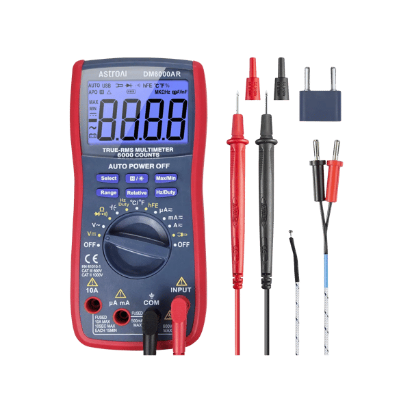
Reference Model Used in This Guide
AstroAI DM6000AR — 6000-count True-RMS Digital Multimeter
The AstroAI DM6000AR is a 6000-count True-RMS digital multimeter designed for common home, automotive, and electronics troubleshooting. It supports AC/DC voltage, AC/DC current up to 10A, resistance, continuity, diode testing, capacitance, frequency, duty cycle, and temperature measurement. True-RMS measurement helps improve AC accuracy on many non-sinusoidal signals within the meter's rated specifications. Manual and auto range selection, backlight, flashlight, auto power-off, Max/Min Hold, Relative measurement, Data Hold, and a low battery indicator are also included.
Key Specs
- 6000-count · True-RMS
- DC 1000V / AC 750V
- DC & AC current to 10A
- Resistance to 60MΩ
- Capacitance: 60μF–20mF
- Frequency: 0–60MHz
- Temperature measurement supported; check the user manual for exact thermocouple range
- Dimensions: 8.66 × 2.28 × 6.69 in | 12.59 oz
- Check the CAT rating printed on your meter and test leads before measuring mains or high-energy circuits
Best for
- Basic home voltage and continuity checks within the meter rating
- Car owners diagnosing battery & alternator
- Automotive 12V checks
- Electronics hobbyists testing components
Not ideal for
- Professional high-energy industrial panels
- EV traction battery or other high-voltage service work
- Clamp-style current measurement or current above 10A
- Users who need advanced functions not listed for the DM6000AR, such as NCV, LoZ, VFD/VFC/LPF, or hFE transistor testing
Summary
A multimeter looks complicated until you understand that it is really three things in one enclosure: a voltmeter, an ammeter, and an ohmmeter, with a few bonus functions bolted on. The dial selects which one you use. The probe jacks tell the meter where the signal comes in. The display tells you the result — and the small icons around the number tell you which mode is active and whether anything unusual is happening. Once those three zones make sense, every measurement follows the same pattern: select the right function, put the red probe in the right jack, apply the probes to the right points, and read the number.
The most important habits to build are simple: start by identifying whether the circuit is live, move the red probe to match the function, measure current only in series, and turn the meter off when you are done.
Browse All AstroAI Multimeters →Frequently Asked Questions
These answers cover the questions beginners usually ask after learning the symbols and probe jacks. For model-specific limits, always check the rating printed on the meter and the official user manual.
What is the first thing a beginner should do before using a multimeter?
Start by confirming the circuit type, the expected range, and the correct probe jack. For unknown or live circuits, begin with voltage mode and make sure the meter and probes are rated for the task. If the circuit involves wall power, a panel, or high voltage, get trained help before testing.
What jack should the red probe go into?
For voltage, resistance, continuity, diode, capacitance, frequency, and temperature checks, the red probe normally goes into the INPUT jack. For current, move the red probe to μA mA or 10A and insert the meter in series with the circuit. Do not use a current jack across a battery, outlet, or power supply.
What is the difference between VDC and VAC?
VDC measures direct-current voltage, such as batteries, USB power, solar panels, and many automotive circuits. VAC measures alternating-current voltage, such as household mains or generator output. Select the mode that matches the source before touching the probes to the test points.
Can I test a car battery with a multimeter?
Yes, a multimeter can check 12V car battery voltage in DC voltage mode. Insert black into COM and red into INPUT, then touch red to positive and black to negative. This checks voltage only; it does not replace a full battery load test.
How do I test continuity?
Turn off and de-energize the circuit first. Set the meter to continuity, place one probe on each end of the wire, fuse, or switch, and listen for the beep. A beep usually means a complete path; no beep or OL usually means the path is open.
Why does my multimeter show OL?
OL usually means the reading is outside the selected range or the circuit path is open. In resistance and continuity modes, OL often means no complete path. In voltage or current modes, stop and confirm the range, probe jacks, and meter rating before continuing.
Can I measure current across a battery?
No. Current measurement must be done in series with a load, not directly across a battery or power supply. Placing a meter in current mode across a power source can blow a fuse, damage the meter, or create a safety hazard.
Is the AstroAI DM6000AR suitable for beginners?
Yes, it is suitable for beginners who want auto-ranging, a large display, common measurement modes, and clearly labeled jacks for basic home, automotive 12V, and electronics checks. It is not a substitute for professional high-energy industrial testing, EV high-voltage battery service, or clamp-style current measurement above 10A.
Sources
- Occupational Safety and Health Administration — "Control of Hazardous Energy (Lockout/Tagout)," general safety reference for controlling hazardous energy before service or maintenance work, accessed Jun 2026. osha.gov
- AstroAI — "DM6000AR Digital Multimeter Product Page," astroai.com. astroai.com
- AstroAI — "Multimeter & Clamp Meter Comparison 2026," astroai.com. astroai.com